[ad_1]
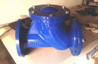
The structure of the safety valve
The safety valve is a kind of automatic valve, which acts on the boiler, pressure vessel and other system pipelines, mainly to control the pressure not to exceed the set value, so as to play an important role in protecting the safe operation of people and equipment. In order to ensure safety, the safety valve must be pressure tested before it can be put into use.
1. Operating conditions of pressure vessels
(1) pressure. The pressure of the pressure vessel can come from two aspects, one is from outside the pressure vessel and the other is from inside the pressure vessel. The higher working pressure of a pressure vessel, for a pressure vessel subject to internal pressure, refers to the higher pressure that may appear on the top of the pressure vessel during normal use; for a pressure vessel subject to external pressure, it refers to the pressure vessel under normal use. During the process, the higher pressure that may occur at the top of the jacket. The design pressure of a pressure vessel refers to the pressure used to determine the thickness of the vessel shell at the corresponding design temperature, that is, the design pressure of the vessel marked on the nameplate, and its value shall not be less than the maximum working pressure. When the static pressure of the liquid column on various parts of the container or pressure components reaches 5% of the design pressure, the sum of the design pressure and the static pressure of the liquid column should be used for the design calculation of the part or component; For pressure vessels, the design pressure shall not be lower than the cracking pressure or bursting pressure of the safety relief device. The design pressure of the container should be determined according to the corresponding provisions of GB 150.
(2) Temperature. Metal temperature refers to the average temperature of the pressure components of the vessel along the thickness of the section. In any case, the surface temperature of the component metal must not exceed the allowable service temperature of the steel. The design temperature refers to the metal temperature of the pressure component set under the corresponding design pressure under the normal operation of the container, and its value shall not be lower than the higher metal temperature that the metal of the component may reach; for the metal temperature below 0~C , the design temperature shall not be higher than the lower metal temperature that the component metal may reach. The design temperature of the container (that is, the design medium temperature marked on the nameplate of the container) refers to the design temperature of the shell.
(3) Medium. There are many kinds of process media involved in the production process, and there are many classification methods. Classified according to the state of matter, there are gas, liquid, liquefied gas, simple substance and mixture, etc.; classified according to chemical properties, there are four types: flammable, flammable, inert and combustion-supporting; according to their degree of toxicity to humans, they can be divided into extreme hazards ( I), high hazard (Ⅱ), moderate hazard (Ⅲ), mild hazard (IV) four levels. Flammable medium: refers to the gas whose lower explosive limit mixed with air is less than 10%, or the difference between the upper and lower explosive limits is greater than or equal to 20%, such as monomethylamine, ethane, ethylene, etc. Toxic medium: The “Pressure Vessel Safety Technology Supervision Regulations” (hereinafter referred to as “Regulations”) divides the degree of medium into four levels according to GB 5044 “Classification of Hazard Degree of Occupational Exposure to Toxic Substances”. The higher allowable concentrations are: extremely hazardous (level I)
2. Classification of pressure vessels.
There are many ways to classify pressure vessels. In order to facilitate safety technology supervision and management, the “Regulations” divides pressure vessels into 3 categories.
(1) One of the following situations is the third category of pressure vessel: high-pressure vessel; medium-pressure vessel (limited to extremely toxic and highly hazardous medium); medium-pressure storage vessel (limited to flammable or moderately hazardous medium) , and pV greater than or equal to 10MPa·m3); medium-pressure reaction vessels (only for flammable or moderately hazardous media with a pV greater than or equal to 0.5MPa·m3); low-pressure vessels (only for extremely and highly toxic media Hazardous medium, and pV is greater than or equal to O.2MPa m3); high-pressure, medium-pressure shell-and-tube waste heat boiler; medium-pressure glass-lined pressure vessel; high service strength level (referring to the lower limit of the specified value of tensile strength in the corresponding standard is greater than or equal to 540MPa) pressure vessels; mobile pressure vessels, including railway tank cars (medium is liquefied gas, cryogenic liquid), tank cars[液化气体运输(半挂)车、低温液体运输(半挂)车、永久气体运输(半挂)车]And tank containers (the medium is liquefied gas, cryogenic liquid), etc.; spherical storage tanks (volume greater than or equal to 50m3); cryogenic liquid storage containers (volume greater than 5m3).
(2) One of the following situations is a Class II pressure vessel: medium-pressure vessels; low-pressure vessels (limited to extremely toxic and highly hazardous media); low-pressure reaction vessels and low-pressure storage vessels (limited to flammable or moderately toxic media) Highly hazardous medium); low-pressure shell-and-tube waste heat boiler; low-pressure glass-lined pressure vessel.
(3) Low-pressure vessels are Class I pressure vessels.
safety accessories
1. Safety valve
The safety valve is an automatic pressure relief valve opened by inlet static pressure. It relies on the pressure of the medium itself to discharge a certain amount of fluid to prevent the pressure in the container or system from exceeding the predetermined safety value; when the pressure in the container returns to normal, the valve closes itself and prevents the medium from continuing to discharge. Safety valves are divided into full-open safety valves and micro-open safety valves. According to the overall structure and loading method of the safety valve, it can be divided into four types: static weight type, lever type, spring type and pilot type.
2. Bursting disc
The bursting disc device is a non-reclosing pressure relief device. The static pressure at the inlet causes the bursting disc to burst under pressure and release the medium, so as to prevent the pressure in the container or system from exceeding the predetermined safety value. Bursting disc, also known as bursting membrane or explosion-proof membrane, is a fractured safety relief device. Compared with the safety valve, it has the characteristics of simple structure, fast pressure relief response, good sealing performance and strong adaptability.
3. Combination of safety valve and bursting disc device
When the safety valve is combined with the bursting disc device in parallel, the rated bursting pressure of the bursting disc shall not exceed the design pressure of the vessel. The opening pressure of the safety valve should be slightly lower than the rated bursting pressure of the bursting disc. When a bursting disc device is installed in series between the safety valve inlet and the container, the following conditions shall be met: the discharge capacity of the combination of the safety valve and the bursting disc device shall meet the requirements; the discharge area of the ruptured disc shall not be less than the area of the safety valve inlet At the same time, it should be ensured that the fragments that cause the bursting disc to rupture do not affect the normal operation of the safety valve; a pressure gauge, cock, vent or alarm indicator should be installed between the bursting disc device and the safety valve to check whether the bursting disc is ruptured or seeped. leak. When the bursting disc device is installed in series on the outlet side of the safety valve, the following conditions should be met: the medium in the container should be clean and free of adhesive or blocking substances; the discharge capacity of the safety valve should meet the requirements; when the safety valve and the bursting disc When there is back pressure between the valves, the valve can still be opened accurately under the opening pressure; the discharge area of the bursting disc shall not be smaller than the inlet area of the safety valve; a vent pipe or a sewage pipe shall be installed between the safety valve and the bursting disc device to prevent Pressure builds up in that space.
4. Blasting cap
The blasting cap is a thick-walled short tube with one end closed and a weak section in the middle. The blasting pressure error is small and the discharge area is small. It is mostly used in ultra-high pressure vessels. When overpressure occurs, the tensile stress on the weak surface reaches the strength limit of the material and fracture occurs. Because it is usually affected by temperature during work, it is generally made of high-strength steel materials (such as 34crNi3Mo, etc.) with stable heat treatment performance and small changes with temperature, and the ratio of burst pressure to material strength is generally O. 2~0.5.
5. Fusible plug
The fusible plug belongs to the “melting type” (“temperature type”) safety relief device. Its action depends on the temperature of the container wall. It is mainly used in small pressure vessels with medium and low pressure. It is more suitable for steel cylinders containing liquefied gases. widely.
6. Emergency shut-off valve, pressure reducing valve
The emergency shut-off valve is a valve with a special structure and a special purpose. It is usually installed in series with the shut-off valve on the medium outlet pipeline close to the container, so as to stop the leakage urgently when there is a large amount of leakage in the pipeline; And the performance of over-temperature shutdown, and can operate independently in short-range and long-range. Emergency cut-off valves can be divided into mechanical (or manual) traction type, oil pressure operation type, air pressure operation type and electric operation type according to different operation methods. The first two types are currently widely used in liquefied petroleum gas tankers. . The pressure reducing valve is a valve that uses sensitive elements such as diaphragms, springs, and pistons to change the gap between the valve disc and the valve seat. When the medium passes through, it will throttle and reduce the pressure to reduce the pressure. When the adjusting bolt is tightened downwards, the spring is compressed, pushing the diaphragm downwards and opening the valve disc of the pulse valve, and part of the medium on the high pressure side enters through the high pressure channel, and flows in through the gap between the valve disc and the valve seat of the pulse valve. The annular channel enters the cylinder, pushes down the piston and opens the main valve disc, at this time the medium on the high pressure side flows through the gap between the main valve disc and the valve seat to be throttled and decompressed. At the same time, a part of the medium on the low-pressure side enters the space under the diaphragm through the low-pressure channel. When the pressure of the medium on the high-pressure side rises enough to offset the spring force, the diaphragm pushes the valve disc of the pulse valve upward and gradually closes. The medium entering the cylinder is reduced, the piston and the main valve disc move upward, and the main valve is closed, thereby reducing the amount of medium flowing to the low-pressure side, so that the pressure on the low-pressure side will not rise due to the increase in the pressure on the high-pressure side, thereby achieving automatic pressure regulation the goal of.
7. Pressure gauge, thermometer, liquid level gauge
(1) Pressure gauge.
The pressure gauge is an instrument that indicates the pressure of the medium in the container and is an important safety device for the pressure container. According to its structure and principle of action, pressure gauges can be divided into four categories: liquid column type, elastic element type, piston type and electric quantity type. Piston pressure gauges are usually used as standard instruments for calibration, liquid column pressure gauges are generally only used to measure very low pressures, and various types of elastic element pressure gauges are widely used in pressure vessels.
(2) Liquid level gauge.
The liquid level gauge, also known as the liquid level gauge, is an instrument used to observe and measure the change of the liquid level in the container. Especially for containers containing liquefied gases, liquid level gauges are an essential safety device.
(3) Thermometer.
A thermometer is an instrument used to measure the degree of heat or coldness of a substance. It can be used to measure the temperature of the medium in a pressure vessel. For a vessel that needs to control the wall temperature, a thermometer for testing the wall temperature must also be installed.
The above seven safety accessories completely explain the structure of the safety valve. I believe that after reading the above, you have a basic understanding of the structure of the safety valve.
[ad_2]