Control Valve Manufacturers
Lucky6s control valve manufacturers produce quality control valves to help you with water treatment. A control valve system consists of an actuator, valve body, positioner, and accessories. It is designed to withstand static and differential pressure fluid flow while supporting the exterior seats. The control valve regulates the flow of fluid and the positioning of the valve disc and plugs without changing the actuator.They are useful for controlling fluctuating processes where an ideal setpoint is possible. Setpoints of the controllers are pressure, temperature, and flow rate. Product restrictions such as liquid level, density, and concentration are observed by the control valve.You can rely on Lucky6s control valve manufacturers to provide you with the best control valves to ensure smooth fluid flow in your applications. Also known as a modulation valve, a control valve is a current-driven device used to control the flow or pressure rate of a system. Regulating valves regulate flow in various degrees from the minimum flow to full capacity. They are equipped with actuators that change the position and closing mechanism of the control valve. The control valve reacts to signals from the control station.It controls the flow of media and the movement of its disc plug (s) according to the opening (s) in its body. The plug is connected to a shaft that is connected to the actuator. The actuator controls the shaft movement according to the instruction of the control valve. It responds to signals coming from an external controller. The control valve and the external control form a control loop.
Considerations for Buy Control Valves:
There are numerous types of control valves, each with their own set of advantages and disadvantages. Determining which control valve is appropriate for your application is dependent on the specific functions they must perform, such as:
Using the Control Valve
A control loop consists of a controller, sensing component, and control valve. A sensing component is in charge of signal transmission to a DCS (distributed control system) or a single controller.
The controller examines the setpoint and signal, and then sends a signal to the valve to make any necessary adjustments. The sensing component confirms the adjustment. As a result, the control loop is complete.
An effective control valve must achieve the following:
• A broader rangeability, which means it must be able to function over a variety of flows;
• Show the least amount of hysteresis or dead time;
• Accurately respond to signals within its operational range;
• React with the appropriate stroking speed;
• Appropriately respond to additional adjustments
A positioner could be added for more precise control. This device boosts the valve’s performance by enhancing the controller’s signal. As a result, a more accurate response is obtained. This also aids in controlling the effects of any friction between the valve and stem, resulting in improved sealing.
A control valve’s quality can be measured in terms of its time constant, dead-time lag, and gain. The gain is the most important of these three factors.
Materials
You have to consider when you buy control valves, you have to consider the trim, hard body, seal and packing, and soft gasket materials. As a standard requirement, the trim and body must be compatible with the materials of the connecting pipeline. Aside from cost considerations and client specifications, the fluid flow properties should also be considered. Take note of whether the application is handling corrosive or erosive media. The internal parts of the valve can be hard-faced with chromium-cobalt alloys or nickel to slow erosion. Furthermore, high-temperature (>800°F) and low-temperature (below freezing point) applications must be taken into account. A control valve, for example, is subjected to increased leakage and stress as a result of internal parts expanding at high temperatures. Fluids that pass quickly through the control valve may cool to temperatures below zero. This is especially true when dealing with high-pressure hydrocarbon fluids. To inspect the outlet temperature at low pressure, a flash computation should be performed. Other low-temperature applications, such as atmospheric moisture and cryogenic fluids, cause the control valve’s moving parts to freeze, rendering it inoperable.As a result, a control valve used in such conditions must be insulated. The body and packing must be built to withstand high pressure. Graphite is used in applications with pressures greater than 1,000 psi to aid soft packing and prevent extrusion in small openings.
Design Features
Identifying the system and flow properties will aid in the selection of the appropriate control valve. The specified maximum flow rate must include the proper design margin, which is typically 10%. When determining the maximum flow rate, the following factors must be considered: system size, pipe schedule number, geometry, and construction materials.
Flow Coefficient
The flow coefficient is the most important factor in determining the size of a control valve. The flow coefficient is calculated based on whether the process flow is compressible, incompressible, or mixed. There are formulas for determining these characteristics, which allow for accurate measurement of valve size.
Flow Characteristics
The following are some factors to consider when determining which flow characteristic is appropriate for your application: Equal Percentage • When the majority of a control system’s pressure drop is caused by the control valve; • When the majority of a control system’s pressure drop does not occur through the control valve; • When it is expected that the pressure drop across the control valve will remain constant; • For linear pressure and temperature control loops; and For liquid-level or flow-control services. Fast Opening Such deluge systems are used for repeated on/off operations, such as semi-continuous services, or when a large amount of flow is required quickly.
Bonnet and Trim
Bonnet A bonnet is a control valve component that encloses the valve packing and actuator. A bonnet is typically designed to accommodate a variety of temperature ranges. As a result, special considerations must be made when selecting the appropriate bonnet for your control valve.An extended bonnet is used in extreme temperatures, such as 450°F, and in temperatures below freezing. This type of bonnet keeps the valve packing away from critical temperatures. An extended bonnet isolates the stem-valve packing from the subzero flow in cryogenic service. This protects the packing from damage. Trim The internal components of a control valve that come into contact with the process flow are referred to as trims. The bonnet, packing, and bottom gaskets and flanges are not included in the trim. A trim keeps the connection between valve-plug lift and flow capacity stable. It also ensures that the control valve is closed properly. The seat is primarily in charge of achieving a tight shut-off. A tight shut-off and proper lift, on the other hand, are dependent on other components of the control valve. These include actuator design, valve-stem packing, and valve body shape. The preferred level of tight shut-off is determined by the service. The percentage of leaks in the flow when the control valve is closed is used to calculate shut-off. Various industry standards specify the requirements for shut-off for a variety of applications. ANSI/FCI 70-2-1998 (3), also known as Control Valve Seat Leakage, is a common standard for determining leakage classes. These classes range from Class II (weak shut-off) to nearly zero leakage (Class VI). The operator configures the TSO or tight shut-off requirement in one of the classes based on the application requirements (in most cases, Class IV, V, or VI are chosen). The valve trim is primarily chosen based on the following factors: fluid operation conditions, basic flow characteristics for a specific trim (as specified by the manufacturer), and the effects of various operating conditions on the basic flow characteristics. These factors indicate the flow characteristics of a trim and are used as a guideline when selecting the appropriate trim. A lower trim allows for more accurate control of low flows while still allowing for high flows in the near future. The design of this trim reduces the flow through the valve opening. However, because of the shorter distance between the plug and the lift, flow control is more precise. There is no rule stating that a reduced-capacity trim must be used at a rate lower than a certain turndown rate. However, when accurate control is required at 20% to 25% of valve capacity, a reduced trim may be an excellent solution. Cages are commonly used in trims because they provide several benefits: A cage can be designed to ensure that fluid forces on the stem and plug are distributed evenly. This design yields a well-balanced, cage-guided trim. A cage guides the plug to ensure it is properly positioned and makes proper contact with the valve seat. A cage can be used to modify the control valve’s original flow characteristics. The stem and plug of a sliding-stem valve are subjected to pressures that can interfere with actuator control. As a result, high dead-bands and improper stem movement may occur. The fluid surrounding the stem has the ability to lift it up, either sideways or downward, and may even apply torsional pressure. Several trim designs are available to balance and counteract these pressures. A balanced trim distributes and balances pressure by adjusting the plug or using a cage-guided trim. Noise Noise is produced by a control valve as a result of aerodynamic effects, mechanical vibrations, or cavitation. Unsteady flow, pressure oscillations, and high velocities produce vibrations that are typically less than 100 decibels (dB) (decibel). A decibel is the maximum level of sound strength from the earphones of a portable radio. The degree of noise produced by cavitation varies. Increased pressure drop through a control valve causes more noise. In full cavitation, a control valve makes a rattling noise.
Control Valve Size and Type
Once the type of valve and flow characteristics have been determined, an initial size can be specified by calculating the valve’s stroke for each design flow. A valve stroke is the ratio of a valve’s actual flow capacity to its computed flow capacity. Choose a valve type that operates between 10% and 80% of the valve stroke through the anticipated operation range. Choosing the Right Size and Type of Control Valve: Pressure drop in a pumped circuit to a control valve must be equivalent to one-third of the dynamic losses in a process system at 15 psi or rated flow, whichever is greater. The pressure drop distributed in a control valve from a centrifugal compressor’s discharge or suction line must be equal to 50% of the system’s dynamic losses or 5% of the actual suction pressure, whichever is greater.Pressure drop in a control valve in steam lines to process vessels, reboilers, and turbines must be 5 psi or 10% of the actual pressure of the steam system, whichever is greater.In an operation where static pressure transfers fluid from one pressure container to another, the pressure drop distributed to a control valve must be 50% of the process system’s dynamic losses or 10% of the lower-terminal container pressure, whichever is greater.The valve’s gain cannot be less than 0.5.Do not use the upper 90 percent or lower 10% of the valve stroke. When a valve is between 10% and 80% open, it is easier to control.
End Connection Types
End connections for a control valve can vary. The RF, or raised face, is the most commonly used. In several high-pressure classes, an RTJ, or ring-type joint, is common. To achieve a tight connection, a control valve can be welded. Welding a valve into place eliminates the weight and cost of flanges. It may, however, become a problem if the valve needs to be removed for maintenance or repair.
Port Classification
A reduced-port control valve is more commonly used than a full-port control valve. This is due to the fact that a smaller port generates a pressure drop that can achieve the required flow capacity. Furthermore, a reduced port is less expensive because it can accommodate a smaller valve body. Prevent asking for unusual valve sizes such as 2.5, 3.5, and 22. These are difficult to find and maybe more expensive than standard sizes.
Maintenance
When a control valve is poorly designed, it may require more maintenance because it cannot function properly under certain service conditions. Wear of the seat, packing, actuator diaphragm, and valve body are all potential issues. The likelihood of these issues can be reduced by selecting the appropriate control valve design and materials. A control valve that handles mixed liquids and solids, for example, should be cleaned on a regular basis to remove dirt. In this case, a globe valve might not be the best option because dirt could enter through the stem seal. This may limit control and possibly damage the valve. A rotary valve, on the other hand, might be a better option. Friction between the valve stem and the packing can cause wear. When compared to a rotary stem, a sliding stem typically causes more packing wear. This is because a sliding stem collects deposits and may transport them through the valve packing. A metal seat is preferred for services that may cause erosion. If a soft seat is required, it must be positioned so that it is shielded from the flow path. If the seat and plug do not make good contact, lapping the seat may be a good solution. Lapping is only possible with a metal seat. It is a manual process in which the seat and plug are ground together so that their surface finishes match. This method can result in a leak-free connection. Furthermore, choosing a control valve with distinguishing features may aid in lowering maintenance. Smart positioners and valves send specific parameters to software, such as stem travel and actuator pressure. These parameters are used by this software to calculate performance indicators such as torque and stem-packing friction.
Valves that are used as control valves
A control valve is available in a variety of valve bodies with varying styles, sizes, connections, and materials. Choosing a control valve heavily relies on the application’s load characteristics, service conditions, and the task the valve performs. The following valves are commonly used as control valves:
Rotary Control Valves
Ball Valves
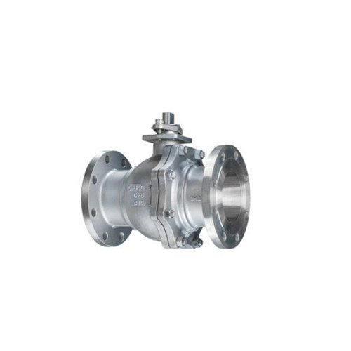
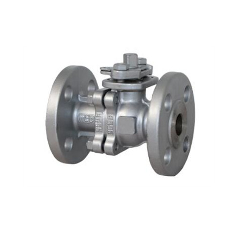
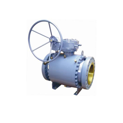
A ball valve is a fast-acting rotary valve with a very tight shut-off. When it is completely open, it creates the least amount of resistance or turbulence to flow. A standard ball valve conforms to ASME face-to-face dimensions, making this valve type easy to modify and replace. A ball valve is classified as a high-recovery valve because of its high flow capacity and low-pressure drop. The ball valve’s stem rotates a disc or plug, also known as a ball with a center opening. This opening can be adjusted to be completely open or closed. It is not ideal for throttling flow because abrasion may cause the ball to wear faster. This could result in leakage when the ball valve is closed. However, in some cases, a ball valve with diagnostic features may be used for throttling. A ball valve is used in a variety of industrial applications due to its leak-proof sealing. Oil and gas industries, pulp and paper industries, and water and wastewater treatment facilities are examples. It is also widely used in high-temperature chemical applications involving oxygen, dry chlorine, and hydrofluoric acid. Some of the additional benefits of using a ball valve include, but are not limited to: • Less costly • Easy to care for • Able to withstand high pressures and temperatures • Easy to use and automate

Butterfly Valve
A butterfly valve is made up of a disc that is connected to a shaft that has bearings to aid in rotation. It is primarily used for basic throttling and when a positive shut-off is not critical. Because only the valve disc blocks the flow path, this valve type is also known as a high-recovery valve. As a result, there is a low pressure drop and a high flow capacity. When fully open, a butterfly valve creates the least amount of resistance or turbulence in the flow. A butterfly valve is well-suited for large line sizes, such as 8” and up, due to its design. Additionally, it meets ASME pressure ratings and face-to-face dimensions. This makes it simple to modify a butterfly valve even when it is in use. A butterfly valve is commonly found in large lines in water treatment plants, fire protection systems, and chemical services. This valve type can also withstand high pressures and temperatures, depending on its materials and design. A butterfly valve also has the following advantages: • Superior flow control • Less expensive and requires less upkeep. • Continued use is advised. • In the process line, there is little fluid trapping.
Eccentric Plug Valve
Another type of rotary control valve is an eccentric plug valve, which has a plug-shaped component that restricts media flow. When rotated, this component follows an eccentric path. Until the plug rotates to within a certain degree of the shut-off position, it has no direct contact with the valve seat. When the plug contacts the valve seat, the seating surfaces align, resulting in a positive shut-off. When dealing with critical service conditions such as erosive fluids and coking, an eccentric plug valve is frequently used. It is also used in the case of slurries. This rotary valve is used for both on-off and throttling functions. An eccentric plug valve is commonly found in the petroleum refining, mining, pulp and paper, and power generation industries.
Linear Control Valves

Gate Valve
A gate valve is a type of linear motion valve that is primarily used to allow or prevent media flow. Its closing element is a wedge-shaped disc, which ensures a tight seal. Surface build-ups, scales, slurries, and other viscous fluids can be cut through with a gate valve. A gate valve is thus ideal for handling air, gas, oil, steam, heavy fluids, non-condensing gases, corrosive and abrasive fluids, and so on. The main benefit of a gate valve is that it allows for full unobstructed flow, allowing for a high flow capacity. Aside from slurries and other viscous fluids, a gate valve can safely allow rocks and other large objects found in mining operations to pass through. A gate valve is commonly found in mining industries, water and wastewater plants, processing plants, power plants, oil and gas industries, chemical processes, food and beverage industries, and other industries due to this feature.
Globe Valve
In a typical globular body, a globe valve consists of a movable component and a fixed ring seat. The stem moves the plug, which can be fully open, semi-open, or fully closed. It is used to throttle and shut off the flow through the globe valve. The globe valve has excellent flow regulation properties due to the body and seat construction. A globe valve may be equipped with a variety of design options, such as actuators, limit switches, positioners, and other necessary accessories. When a globe valve is fully opened, turbulent flow passes through the plug and seat. This means that a globe valve is well-suited to applications where pressure drop isn’t an issue. A globe valve is capable of handling a wide range of fluids, including vapors, liquids, and gases. It is also used when dealing with corrosive substances. A globe valve is frequently used in applications that require precise flow regulation and continuous wide throttling. It is also used in applications requiring extremely high pressure drops. A globe valve is used in a variety of industries, including chemical and petrochemical, pulp and paper, power plants, and others, due to its precise throttling.
Diaphragm Valve
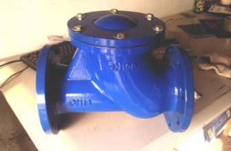
A diaphragm valve gets its name from its flexible disc, which makes contact with the valve seat above the body to form a seal. The flexible disc, also known as the diaphragm, is pressure-responsive and sends a force to control, close, or open the valve. A diaphragm valve can be of one of two basic types: straight-through or weir. The basic structure of both types is very similar. Their bodies and diaphragms, however, are significantly different. In services where the flow direction changes within the processing system, a straight-through diaphragm valve is used. The valve body’s bottom is flat and parallel to the media flow. This allows the flow to move freely with no major impediments. The most common type is a weir diaphragm valve, which is ideal for general applications as well as abrasive and corrosive applications. It’s also used to control minimum flows. This valve type’s body has an elevated lip that makes contact with the diaphragm. This valve has a smaller diaphragm because it does not need to stretch as much.
The Various Types of Control Valves
Control valves are available in a variety of designs, materials, and accessories. As a result, determining which control valve is appropriate for your application can be difficult. It is essential that you make an informed decision. Choosing the wrong valve could cause serious issues with the entire system. We’ve divided control valves into groups to help you find what you’re looking for. This is to assist you in making the best choice and avoiding system problems as much as possible.
Control Valve classified by Actuation

Electric Control Valve
An electric control valve is activated by a motor-driven device known as an electric actuator. It generates a motorized shaft rotation using an electric signal. This rotation is then converted into linear motion by the unit’s connection, allowing the plug and stem to control flow. If the electric signal fails, this actuator can be set to fail in its last, stem-in, or stem-out position. Servo motors and step motors are two common types of electric actuator motors. 1. Servo MotorA servo motor has a closed-loop that optimizes performance at higher speeds. It has anti-backlash mechanics and high-precision screws with accuracies down to thousandths of an inch. This type of motor, however, is more expensive than a step motor. 2. Step MotorA step motor employs gears with special additions in the 5,000 to 10,000 range at a 90-degree rotation for precise positioning at low speeds. Brush DC and AC motors are sometimes used with limit switches when positioning accuracy is not critical. The motor is connected to a thread or gear that generates thrust to move the valve. The torque-sensing mechanism of an electric actuator shuts down the motor when it exceeds the specified torque level for valve protection.Position switches are also used to determine the position of valves. In many cases, a hand wheel and declutching mechanism are installed to allow manual operation of the valve in the event of a power outage.
Pneumatic Control Valve
A pneumatic actuator is used to operate a pneumatic control valve. To generate action, this type of actuator uses a compressed air signal from an external control device. It is commonly available in two basic forms: diaphragm actuators and piston actuators. Actuator DiaphragmCompressed air is forced through a flexible disc known as the diaphragm in a diaphragm actuator. This type of actuator is single-acting, which means that air is supplied to only one side of the diaphragm. A diaphragm actuator can be either direct or reverse acting. Direct-acting (spring-to-react) When the diaphragm pressure rises, the valve stem in a direct-acting diaphragm actuator extends. This mechanism closes the control valve, which is why it is also known as the “air to close” mechanism.Acting in reverse (spring-to-extend)When the diaphragm pressure rises, the valve stem lifts in a reverse-acting actuator. The valve will open in this case, which is why it is also known as “air to open.”Actuator with a PistonWhen the thrust is limited or the stroke of the actuator is too short, a piston actuator is commonly used in services. Compressed air is applied to a piston contained within a long-lasting cylinder. This actuator can be either single-acting or double-acting. A piston actuator can withstand higher pressures and provide small cylinder volumes that can act at a faster rate.

Solenoid Valve
A solenoid valve is a type of control valve that opens or closes process flow by being electrically activated or deactivated. It is commonly used in hydraulic and pneumatic systems to control the direction of the flow of liquid or air.
Control Valve classified by Media Type
Control Valve for Water
A water control valve is intended to regulate the properties of water such as cold water, hot water, ground water, salt water, potable water, or wastewater.


Control Valve for Steam
A steam control valve, as the name implies, is primarily used to control steam in a variety of applications. This control valve’s primary function is to regulate the inlet steam pressure for process operations. This valve, however, can also be used to control temperature.
Control Valve classified by Number of Ports
Two-way Control Valve
A two-way control valve has two openings or ports – an inlet port and an outlet port. These ports are commonly denoted as A and AB. A two-way control valve is used to provide basic on/off services in a variety of industrial applications. With the addition of special design features, it can also be used for other complex services.


Three-Way Control Valve
A three-way control valve is one that has three ports labeled A, B, and AB. In constant volume or flow pumping systems, a control valve with three openings is commonly used. It can be used as a diverting or mixing valve. This valve can be installed at either the return or supply end of the pipe. A diverting valve has one port on the supply end of the pipe and two ports on the return end. A mixing valve, on the other hand, has two ports on the supply end and one on the return end. The primary function of this type of valve is to mix two fluids before they are transferred to another vessel or container.
Four-way Control Valve
A four-way control valve has four openings evenly spaced within the valve’s chamber. It is widely used in pneumatic systems for directional control. The plug, which can be a ball or a plug (tapered or cylindrical), has two passages that allow the adjacent openings to be connected. This type of valve is commonly used in industrial applications that handle clean air, liquefied petroleum gas, natural gas, hydraulic oils, petroleum-based lubricants, and other fluids.

Control Valve classified by Application

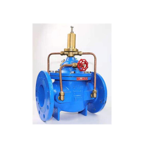
Pressure-reducing Valve
A pressure-reducing valve is a type of control valve that converts a high inlet pressure to a fixed downstream pressure. This is true regardless of fluctuations in supply and demand. It enables fluid transmission at safe pressures and levels in a variety of operations such as irrigation systems, fire systems, and main feed lines. A pressure-relief valve is frequently misidentified as a pressure-reducing valve. There is a distinction between the two. A pressure-relief valve is used to relieve a system’s or vessel’s excess pressure. It only works when the pressure is dangerously high. Meanwhile, in pneumatic and hydraulic circuits, a pressure-reducing valve is used to reduce pressure. It will reduce pressure even if the allowable pressure level rises only slightly.
Pressure-relief Valve
A pressure-relief valve is used to relieve excess pressure while maintaining control of a low upstream pressure. It prevents downstream demand from jeopardizing upstream demand. A pressure-relief valve’s primary function is to keep the entire system safe in order to protect personnel and prevent serious accidents. When there is an overpressure event, a pressure relief valve protects the pressurized system or vessel. An overpressure event occurs when pressure exceeds the specified limit. This is accomplished by programming the pressure-relief valve to open at a specific pressure level. It then closes when the pressure in a vessel’s system returns to a safe level.A pressure-relief valve is commonly used at pump stations to protect in-line distribution pipes.

Cryogenic Control Valve
A cryogenic control valve is designed specifically for cryogenic services at temperatures as low as -325°F (-198°C). To withstand harsh service conditions, this control valve is typically made of stainless steel. It also has an extended bonnet to protect the stem-valve packing from the high temperatures of the process flow.At very low temperatures, a cryogenic control valve is used to provide both on/off and throttling control of gases and liquids. It is commonly used in special operations in the chemical industry and hydrocarbon processing, such as the production of liquefied natural gas.
High-pressure Control Valve
A high-pressure control valve is designed for high-pressure and high-temperature applications. It typically has a compact body to achieve low pressure loss. It also includes a stabilizer to control the turbulence around the cage. A high-pressure control valve with these features allows for a large flow capacity and improved flow characteristics.A high-pressure control valve is made of durable materials because it is used in harsh working conditions. Because of the increased strength of the material, it is usually made of stainless steel. If cost is a consideration, a high-pressure control valve is typically made of chrome-molybdenum. It is also a more durable and less expensive material than stainless steel.
Temperature Control Valve
A temperature control valve can be used in two ways. To begin, it can be used to mix hot and cold fluids in various amounts depending on the needs. The operator can control the final temperature of the fluid by increasing the levels of hot or cold fluid. In many cases, the cold fluid output is adjusted to change the temperature of the fluid.Second, a temperature control valve may be used in conjunction with a heat exchanger, which is a device that changes the temperature of a process fluid by using cold or hot fluids. Because these fluids are separated by housing or pipes, there is no direct contact between them.
There are two types of welded connections:
Socket WeldThe socket-shaped welded end of the ball valve is where the pipe is placed and welded into the ball valve. This connection method is mostly utilized for small valves under two inches in diameter.
Butt WeldTo make a connection, the pipe and valve ends are connected together and then welded together. For jointing, both butt edges are sloped. This connection can be used with any valve size.
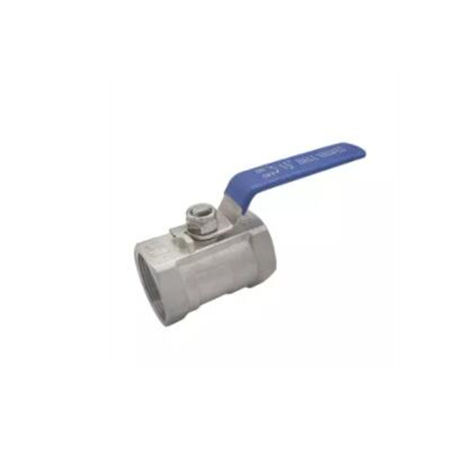
Threaded Ball Valves
A threaded ball valve is one that is attached to the pipeline by pipe threads. This connection method is mostly utilized for small valves with a pressure level of 1 MPa or lower that are less than two inches in diameter. Despite its ease of installation, a threaded connection must meet certain standards in order to be successful. The pipe and valve threads, for example, should be made to the same specification to ensure a correct connection. On a white background, a ball valve with external and internal threads. End connections for thread valves are appropriate for low-pressure pipe systems and plumbing applications, such as water and wastewater. A threaded connection has a significant advantage over other connection types in that it does not require small elements such as nuts and bolts to attach. As a result, the threaded ball valve is both cost-effective and simple to install. Furthermore, a threaded ball valve’s direct and compact connection to a pipeline ensures that leakage is minimized.

Control Valve classified Flow Characteristics
Quick Opening Control Valve
A quick opening control valve increases process flow significantly for a small initial change in stem travel. At a low percentage of the highest stem lift, nearly maximum flow is achieved. It has a valve gain that is too high for modulation in general. As a result, this type is used for one-time services like sequential operations in semi-continuous or batch processes.Control Valve, LinearA linear control valve has flow characteristics that provide a linear relationship between flow rate and valve positioning. The flow path through a linear control valve is directly dependent on the stem position. This means that the flow is straight, with balanced volume changes and balanced lift changes.A linear control valve is widely used in flow control services that require constant gain and liquid level control.
Equal Percentage Control Valve
The flow characteristics of an equal percentage control valve have a non-linear curve, with the slope increasing as the control valve opens. This means that the flow capacity of the valve increases dramatically as the valve stem travels. Equal increments of travel result in equal percentage changes in current flow capacity.
Control Valve classified by Material
Carbon Steel Control Valve
Carbon steel is the most commonly used control valve body material. It can handle almost any non-corrosive gas or liquid at temperatures as high as 800°F for continuous operations and 1000°F for less frequent service. In most steam and condensate applications, a carbon steel control valve is used.
Stainless Steel Control Valve
A stainless steel control valve is a long-lasting valve. Stainless steel is well-known for its high strength and resistance to corrosion and abrasion. A stainless steel control valve is primarily intended for corrosive applications and services involving high temperatures of up to 1000°F. It is more corrosion resistant than other valve materials.
Chrome-molybdenum Steel Control Valve
Another common material for control valves is chrome-molybdenum. This material, also known as chrome-moly steel, allows a control valve to withstand higher pressures and temperatures than a carbon steel valve. In general, chrome-moly steel is stronger than carbon steel and, in some cases, as durable as stainless steel. A chrome-moly steel control valve is frequently used in flashing condensate and high-pressure steam, both of which require resistance to erosion and corrosion.
More To Explore
LUCKY6S is Chinese leading manufacturer and supplier of industrial valves. which has over ten years of experience in manufacturing high-quality industrial valves, focuses on delivering safety, efficiency, and cost-effectiveness to every industry that requires automation. We are committed to supplying premium industrial valves and equipment to distributors, importers, and project managers worldwide.
Facebook
Twitter
Google-plus
Snapchat
Instagram
Valves Manufacturer
- Valve manufacturer
- Our facility
- Quality
- Contact